
OBD-I
The regulatory intent of OBD-I was to encourage auto manufacturers to design reliable emission control systems that remain effective for the vehicle's "useful life". The hope was that by forcing annual emissions testing for California, and denying registration to vehicles that did not pass, drivers would tend to purchase vehicles that would more reliably pass the test. Along these lines, OBD-I was largely unsuccessful—the means of reporting emissions-specific diagnostic information was not standardized. Technical difficulties with obtaining standardized and reliable emissions information from all vehicles led to an inability to implement effectively the annual testing program.
OBD 1.5
OBD 1.5 refers to a partial implementation of OBD-II which General Motors used on some vehicles in 1994 and 1995 (GM did not use the term OBD 1.5 in the documentation for these vehicles - they simply have an OBD and an OBD-II section in the service manual.)
For example, the 94-95 Corvettes have one post-catalyst oxygen sensor (although they have two catalytic converters), and have a subset of the OBD-II codes implemented. For a 1994 Corvette the implemented OBD-II codes are P0116-P0118, P0131-P0135, P0151-P0155, P0158, P0160-P0161, P0171-P0175, P0420, P1114-P1115, P1133, P1153 and P1158.[1]
This hybrid system was present on the GM H-body cars in 94-95, W-body cars (Buick Regal, Chevrolet Lumina ('95 only), Chevrolet Monte Carlo ('95 only), Pontiac Grand Prix, Oldsmobile Cutlass Supreme) in 94-95, L-body (Chevrolet Beretta/Corsica) in 94-95, Y-body (Chevrolet Corvette) in 94-95, on the F-body (Chevrolet Camaro and Pontiac Firebird) in 95 and on the J-Body (Chevrolet Cavalier and Pontiac Sunfire) and N-Body (Buick Skylark, Oldsmobile Achieva, Pontiac Grand Am) in 95.
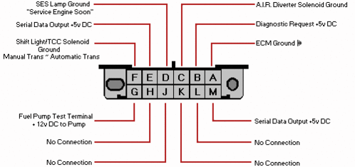
The pinout for the ALDL connection on these cars is as follows:

| 1 | 2 | 3 | 4 | 5 | 6 | 7 | 8 |
| 9 | 10 | 11 | 12 | 13 | 14 | 15 | 16 |
For ALDL connections, pin 9 is the data stream, pins 4 and 5 are ground and pin 16 is battery voltage.
Additional vehicle-specific diagnostic and control circuits are also available on this connector. For instance, on the Corvette there are interfaces for the Class 2 serial data stream from the PCM, the CCM diagnostic terminal, the radio data stream, the airbag system, the selective ride control system, the low tire pressure warning system and the passive keyless entry system.[2]
An OBD1.5 has also been used on Mitsubishi cars of '95 '97 vintage, some 1995 Volkswagen VR6's (Juice Box's GTI), and in the Ford Scorpio since 95.
OBD-II
OBD-II is an improvement over OBD-I in both capability and standardization. The OBD-II standard specifies the type of diagnostic connector and its pinout, the electrical signalling protocols available, and the messaging format. It also provides a candidate list of vehicle parameters to monitor along with how to encode the data for each. Finally, the OBD-II standard provides an extensible list of DTCs. As a result of this standardization, a single device can query the on-board computer(s) in any vehicle. This OBD-II came in 2 models OBD-IIA and OBD-IIB.
OBD-II Diagnostic connector

The OBD-II specification provides for a standardized hardware interface—the female 16-pin (2x8) J1962 connector. Unlike the OBD-I connector, which was sometimes found under the hood of the vehicle, the OBD-II connector is nearly always located on the driver's side of the passenger compartment near the center console. SAE J1962 defines the pinout of the connector as:
- -
- Bus positive Line of SAE-J1850
- Ford DCL(+) Argentina, Brazil (pre OBD-II) 1997-2000, Usa, Europe, etc.
- Chassis ground
- Signal ground
- CAN high (ISO 15765-4 and SAE-J2284)
- K line of ISO 9141-2 and ISO 14230-4
- -
- -
- Bus negative Line of SAE-J1850
- Ford DCL(-) Argentina, Brazil (pre OBD-II) 1997-2000, Usa, Europe, etc.
- -
- -
- CAN low (ISO 15765-4 and SAE-J2284)
- L line of ISO 9141-2 and ISO 14230-4
- Battery voltage
The assignment of unspecified pins is left to the vehicle manufacturer's discretion.
Signal protocols
There are five signalling protocols currently in use with the OBD-II interface. Any given vehicle will likely only implement one of the protocols. Often it is possible to make an educated guess about the protocol in use based on which pins are present on the J1962 connector:
- SAE J1850 PWM (pulse-width modulation - 41.6 kbaud, standard of the Ford Motor Company)
- pin 2: Bus+
- pin 10: Bus–
- High voltage is +5 V
- Message length is restricted to 12 bytes, including CRC
- Employs a multi-master arbitration scheme called 'Carrier Sense Multiple Access with Non-Destructive Arbitration' (CSMA/NDA)
- SAE J1850 VPW (variable pulse width - 10.4/41.6 kbaud, standard of General Motors)
- pin 2: Bus+
- Bus idles low
- High voltage is +7 V
- Decision point is +3.5 V
- Message length is restricted to 12 bytes, including CRC
- Employs CSMA/NDA
- ISO 9141-2. This protocol has a data rate of 10.4 kbaud, and is
similar to RS-232. ISO 9141-2 is primarily used in Chrysler, European,
and Asian vehicles.
- pin 7: K-line
- pin 15: L-line (optional)
- UART signaling (though not RS-232 voltage levels)
- K-line idles high
- High voltage is Vbatt
- Message length is restricted to 12 bytes, including CRC
- ISO 14230 KWP2000 (Keyword Protocol 2000)
- pin 7: K-line
- pin 15: L-line (optional)
- Physical layer identical to ISO 9141-2
- Data rate 1.2 to 10.4 kbaud
- Message may contain up to 255 bytes in the data field
- ISO 15765 CAN
(250 kbit/s or 500 kbit/s). The CAN protocol is a popular standard
outside of the US automotive industry and is making significant
in-roads into the OBD-II market share. By 2008, all vehicles sold in
the US will be required to implement CAN, thus eliminating the
ambiguity of the existing five signalling protocols.
- pin 6: CAN High
- pin 14: CAN Low
Note that pins 4 (battery ground) and 16 (battery positive) are present in all configurations. Also, ISO 9141 and ISO 14230 use the same pinout, thus the connector shape does not distinguish between the two.